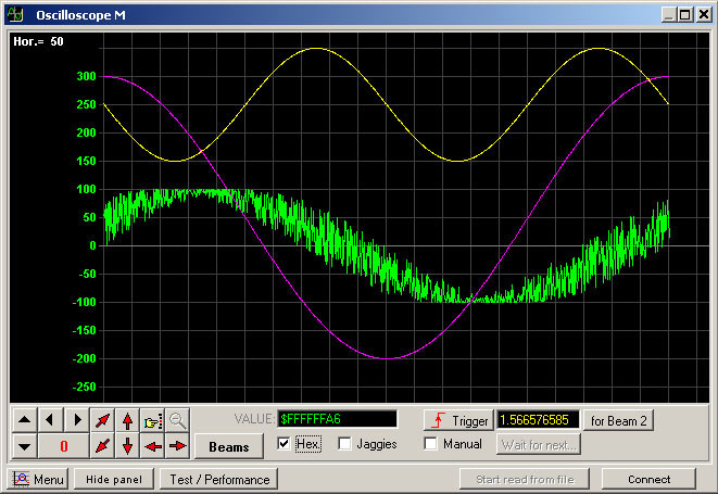
Oscilloscopic graphical user interface screenshot
Free download URL of baseline x86 32-bit and AMD 64-bit.
4.2.0 version 16.8 MB (17,631,233 bytes): Updated June 30, 2021.
Oscilloscope_DLL.zip md5sum: 3650b7f48a499bea90cf29bf839504b7 .
Documentation locates in the Osc_DLL_DOC.txt file inside downloaded archive.
2012 year completely prepared and tested 64-bit ver. with Win7.
2016 year tested 64-bit ver. with MS Windows 10.
The library makes it possible to show on the beams of the oscilloscope over a million quantization steps of signal per second – less than one micro-second is sufficient for one signal sample. This software can be used for linking to real-time controlling programs as longer delays in relay of data to the oscilloscope don’t occur. The relayed data is instantly displayed in beams, the process of their relay and display is deterministic (may be infinite). The relayed data is stored in the oscilloscope memory and can be displayed graphically as beams at any time – without any “solution” such as decimation or excerption, strobe effect and the like. It works regardless of the relay speed.
Convenient integration with any application-orientated software: the on-screen oscilloscope is designed as a DLL exporting 9 functions, of which 4 are usually enough to work with. The library is supplied with a comprehensive description of the program interface and simple examples of its use executed in various different program development environments: MS Visual C++® & Visual Basic®; Embarcadero (Borland) Delphi® & C++Builder®; MathWorks Matlab® & Simulink®, C# (C Sharp), Python and Java.
A viewing oscilloscope is created by this library as a separate window, entirely independent of the program which activated it. This window contains all the elements typical of a control panel of a real oscilloscope. All the control elements are equipped with hints concerning their function. This viewing oscilloscope doesn’t create any additional windows with any secondary controlling elements or indicators. The library can read any indicated ini file (easily edited text format) containing a description of the initial oscilloscope properties including: all graphics such as colours, type and size of fonts, size of grid cells, display/hide control elements options, window caption text, as well as a description of modes: number of beams, time and amplitude scales and offsets for each beam independently, buffer lengths, modes and levels of triggering, etc. Viewing oscilloscope can also save all the current settings onto the given ini file, the format of which is described in detail in applied documentation.
Data already shown in the oscilloscope beams can easily be transferred to other programs via clipboard (copy - paste) in text form or via the saved text file. In order to do this, select any signal fragment on the oscilloscope monitor – as is done in any text editor program. Text format of exported data is universal and simple – it consists of amplitude columns representing the time series. The columns are separated by a tabulation symbol. In such form data can be easily imported into most “spread sheet” kinds of programs – such MS Excel®, as well as into programs of the Matlab® type. The oscilloscope also allows such data file to be loaded quickly onto its beams.
This library employs only the most basic MS Windows API functions and works reliably on all versions of 32-bit MS Windows® starting with the ’95 version. This works good on the MS Windows Vista® and Windows 7® (including 64-bit ver.) as well. Recently the 64-bit ver. of the DLL was successfully tested on 64-bit ver. MS Windows 10. Before its first release this library was developed and robustly tested for over 6 years. During this period it was used in a medical monitoring system, in the automobile industry (engine monitoring), in motion control systems (servo controllers for electric motors) and in metrological studies (development of sensors). Applied software emitting data to this oscilloscope obtained data via such communications as serial port (RS232, 422, 485), SSI, USB, CAN bus, Ethernet, GRIB (instrumental interface), via custom-made communications equipment and also by collecting information via a data acquisition card with analog-to-digital converters mounted on the PCI bus-bar of a PC. The oscilloscope was also connected to receive data flow from a PC sound card. We tested and practically confirmed the possibility of relaying data to the scope directly from the computer’s hardware interrupt procedure (IRQ) and from any kind of anisochronous thread - which is important.